
MAX6652是Maxim美信半导体公司的一款1-Wire器件产品,MAX6652是温度传感器及系统监控器,10引脚µMAX封装,本站介绍了MAX6652的封装应用图解、特点和优点、功能等,并给出了与MAX6652相关的Maxim元器件型号供参考。
MAX6652 - 温度传感器及系统监控器,10引脚µMAX封装 - 1-Wire器件 - 温度传感器及系统监控器,10引脚µMax封装 - 美信半导体
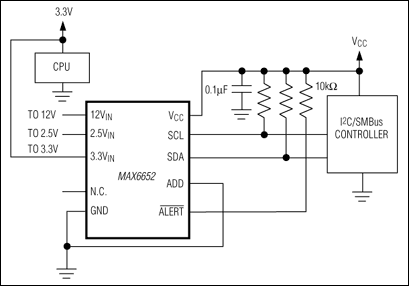
The MAX6652 system supervisor monitors multiple power-supply voltages, including its own, and also features an on-board temperature sensor. Voltages and temperature are converted to an 8-bit code using an analog-to-digital converter (ADC). A multiplexer automatically sequences through the voltage and temperature measurements. The digitized signals are then stored in registers and compared to the over/under threshold limits programmed over the 2-wire serial interface.
When a temperature measurement exceeds the programmed threshold, or when an input voltage falls outside the programmed voltage limits, the MAX6652 generates a latched interrupt output active-low ALERT. Three interrupt modes are available for temperature excursions: default mode, one-time interrupt mode, and comparator mode. The active-low ALERT output is cleared, except for temperature interrupts generated in comparator mode, by reading the interrupt status register (Table 5). The active-low ALERT output can also be masked by writing to the appropriate bits in the interrupt mask register (Table 6) or by setting bit 1 of the configuration register (Table 4) to 0. The MAX6652 I²C*-compatible/SMBus™ interface also responds to the SMB alert response address.
The 2-wire serial interface accepts both I²C and standard system management bus (SMBus) write byte, read byte, send byte, and receive byte commands to program the alarm thresholds and to read voltage and temperature data. Voltage data is scaled so that when the nominal voltage is present at a pin (e.g., 3.3V for the 3.3VIN pin), the conversion result is equal to 3/4 of the ADC full-scale range or a decimal count of 192 (Table 3). The temperature data format is 7 bits plus sign, with each data bit representing 1°C, in two's complement format (Table 2).
The MAX6652 has only one address pin, ADD. One of four different address codes can be selected by connecting the ADD pin to GND, VCC, SDA, or SCL. Whenever an I²C-compatible/SMBus transaction is initiated, the two LSBs of the slave address register are determined by connection, setting the chip address to one of four possible values. In addition, an address code can also be directly written to the serial address register. This code will overwrite the code set by connection of the ADD pin, until the MAX6652 is taken through a power-on reset cycle.
The MAX6652 features 60Hz or 50Hz line-frequency rejection for optimal performance. The device operates from +2.7V to +5.5V and is specified for operation from -40°C to +125°C. It is available in a tiny 10-pin µMAX® package.


